


Vacuum System
Vacuum System:
Okay, lets journey through the Vacuum system and some of itĺs components. There is obviously enough stuff in print which goes into great depth about the vacuum system on 68-82 Corvettes. Unfortunately, many donĺt have it. Those that do hate getting descriptions that go on and on and on. Maybe they should come out with a "Corvette Vacuum Systems For Idiots". Lets see if we can simplify some of it for you.
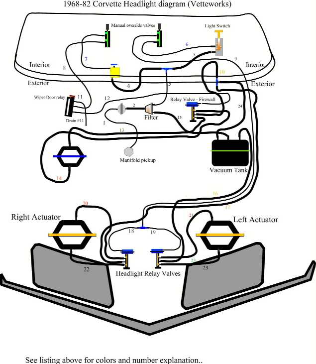
The primary vacuum system consists of 24 different lines which are color coded Red, Green, White, Yellow, blue and black. Your colors may not be visible but this is what they started out as. This system controls the head lights and wiper door assembly on the car. In addition to the primary system, there is an environmental vacuum system which controls the ductwork which directs AC and Heating air depending on the setting selected by the driver at the center shift console AC/Heating control panel.
In the primary system we have three actuators which are each controlled by a proportioning valve which is supplied vacuum pressure from the main vacuum tank. All three main supply lines are large yellow lines which connect to the center of each proportioning valve. One goes to the wiper door actuator, while the other two go to each of the forward proportioning valves located under the skin of your front end. Your Cross Flag emblem is an excellent way to find where this is. They are under it. The proportioning valve for the wiper door is located on the firewall to the left of the distributor. (from drivers seat). They are all the same thing and operate the same way.
Hereĺs what a proportioning valve (prop)doesů
First of all, there is always suction at the center inlet waiting
to go out one of the other two ports. It will either go out the upper or lower port. The thing that makes this determination is the direction of the vacuum introduced to the cap on the proportioning valve. Your light switch, the two manual override switches under your steering column and a wiper door solenoid behind your Tachometer are all thatĺs used to control input to the ports on the caps of the proportioning valves. Because of the small size of the sliding valve inside the proportioning valves, they are fed vacuum pressure through small black lines directly from the manifold. This begins at the little filter located near your brake booster. Itĺs the smaller of the two black lines. The other is the main supply going to the vacuum tank. This suction is introduced to the cap ports of the prop. valves depending on the position of the light switch, solenoid and manual override switches.THE ENTIRE CONTROL OF THE VACUUM SYSTEM IS ACCOMPLISHED BY DIRECTING MANIFOLD PRESSURE INDEPENDENT OF THE MAIN VACUUM RESEVOIR OR SYSTEM SUPPLY. MANIFOLD PRESSURE CONTROLS, WHILE RESERVOIR PRESSURE DOES THE WORK. THIS MANIFOLD PRESSURE IS TAPPED DIRECTLY FROM THE MANIFOLD AND IS DIRECTED TO THE SWITCHES AND SOLENOID WHICH "CONTROL" THE HEADLIGHTS AND WIPER DOOR. IT BEGINS AT THE SMALLER OF THE TWO PORTS ON THE LITTLE ROUND FILTER ABOVE YOUR LEFT VALVE COVER. THE OTHER PORT SUPPLIES VACUUM TO THE VACUUM SYSTEM RESERVOIR THROUGH A SLIGHTLY LARGER LINE. (Black)
Head lights:
Turning on your light switch not only completes the electrical circuit for the lights, it also sends vacuum through your manual headlight override switch. Assuming the override switch is open, the suction will continue down stream to the "T" feeding the tops of each proportioning valve for the headlight doors. It will then pull the spring loaded diaphragm and valve shaft of the proportioning valves upward. This will open the bottom port of the valves, allowing main vacuum pressure to continue its route to the main headlight door actuators. Remember, this main pressure comes from the large yellow line entering the center port of the prop valve. Your headlights should now open. If pressure to the tops of the prop valves is removed because of your switch settings, the valve shafts will slide down, closing the bottom ports while opening the top. Main pressure from the yellow lines will now flow to the opposite side of the headlight door actuators through the upper port of the prop valve. (Upper isnĺt the "cap". Itĺs the upper most of the three lines stuffed next to each other on the valve.) Main vacuum supply connections arenĺt really important when troubleshooting the vacuum system. Reversing the action of the actuators is simply a matter of swapping the upper or lower lines on the proportioning valve. Leaks are your primary concern. Second to this is the physical condition of the components in the system.
Wiper door:
Considering that this system has exactly the same components as the headlight system, we wonĺt duplicate the prop valve details. The difference here is the electrical triggering of the wiper door solenoid. This switch allows vacuum to flow while in the "off" position. As we continue towards the wiper door actuator, we get to the manual override switch/valve. This too allows vacuum to flow in the "off" position. Yes "OFF"ů.but open. Vacuum is then routed to the center of the three ports on thee wiper actuator safety switch located under the right hand wiper arm base. The next place the vacuum arrives at is the top cap of the proportioning valve. Here, it pulls the diaphragm against the spring pressure within the cap, moving the sliding valve upwards, opening the bottom port and allowing "Main" supply pressure from the center port to go through it. The last place in this journey is the forward inlet at the wiper door actuator. Here, it pulls the actuator arm forward, closingů.or keeping closedůthe wiper door. Turning the wiper switch "on" closes the entire path from the solenoid to the upper port on the cap of the proportioning valve. The diaphragm then returns to its resting place, moving the sliding valve down and opening the upper main supply port leading to the opposite side of the wiper door actuator. Now it opens
Wiper safety switch:
We donĺt want the wiper door to close before the wipers have a chance to "Park". The base of the right hand wiper arm pushes down on a piston/valve when parked. This action allows vacuum to continue its path to the upper cap of the wiper door proportioning valve, keeping the door closed. If the wiper arm doesnĺt push down enough the door will remain open, creep open or close slower than normal. When the wiper switch is turned on, vacuum pressure is cut off completely from the safety switch. The proportioning valve diaphragm returns under spring pressure and the Ĺmain supplyĺ vacuum pressure is routed to the aft side of the actuator diaphragm through the lower port of the proportioning valve. This causes the actuator shaft to get sucked back, opening the wiper door.
Manual override switches:
Right smack between of your tachometer and speedometer is a "T" fitting which is fed directly from the filter. mentioned in bold capital letters above. Yes, this is the first branch of the manifold pressure supplying the controlling mechanisms of the system. One side of the "T" feeds your headlight switch. The other feeds the wiper door solenoid controlled by the electric wiper switch. The manual override switches at the bottom of the dash interrupt the continuation of vacuum pressure to the upper caps on the proportioning valves for the headlight and wiper doors. Pulling them down cuts off pressure, allowing the corresponding proportioning valve to re-seat.
AC/Heater:
The vacuum supporting this system is tapped off of Line #10.While troubleshooting the main system, always isolate it from the A/C and heating system. Disconnect and cap this line at the "T" prior to it going through the firewall
Hoses:
1.) Medium Black 4" Intake manifold fitting to Plastic filter
2.) Medium Black 20" Plastic filter to metal valve (near manifold connection)
3.) Small Black 30" Metal Valve to "T" connector under dash
4.) Small Yellow 11" "T" connector to wiper door solenoid
5.) Small Black 18" "T" connector to headlight switch
6.) Small Blue 18" Headlight switch to headlight manual override valve
7.) Small Blue 16" Wiper solenoid to manual override valve (Wiper door)
8.) Small White 52" Wiper manual override valve to wiper arm safety valve(under wiper)
9.) Small White 100" Manual headlight valve to "T" between headlight "prop" valve caps.
10.) Large Yellow 13" "T" connection near reservoir to middle port on wiper door prop valve.
11.) Small Black 15" Wiper safety valve upper port. (Vent line).
12.) Small White 36" Wiper door "Prop" valve cap to bottom port on wiper safety switch.
13.) Large Green 28" Bottom port on wiper "Prop" valve to wiper door actuator rear.
14.) Large Red 31" Upper port on wiper door "Prop" valve to front of wiper door actuator.
15.) Medium Black 17" Plastic filter to vacuum tank. (Reservoir supply)
16.) Large Yellow 77" Reservoir to left headlight "Prop" valve center port. (Supply)
17.) Large Yellow 84" "T" near reservoir to right headlight "Prop" valve center port (Supply)
18.) Small White 14" "T" connector between headlights to RHT headlight "Prop" valve cap.
19.) Small White. 14" "T" connector between headlights to LFT headlight "Prop" valve cap.
20.) Large Red 23" Top port of RHT "Prop" valve to rear of RHT headlight actuator.
21.) Large Red 23" Top port of LFT "Prop" valve to rear of LFT headlight actuator
22.) Large Green 16" Bottom port on RHT "Prop" valve to FWD port on RHT light actuator.
23.) Large Green 16" Bottom port on LFT "Prop" valve to FWD port on LFT light actuator.
24.) Large Black 9" Vacuum reservoir to "T" near reservoir. (About 9" away near fender)
Vetteworks
- J. M.